InfraredHeaters.com Questions? 1-800-442-2581 |
Our secure online
ordering website: www.MorElectricHeating.com.
|
|
| Home | Products | Accessories | Ordering | Contact Us | Search | ||
Salamander 
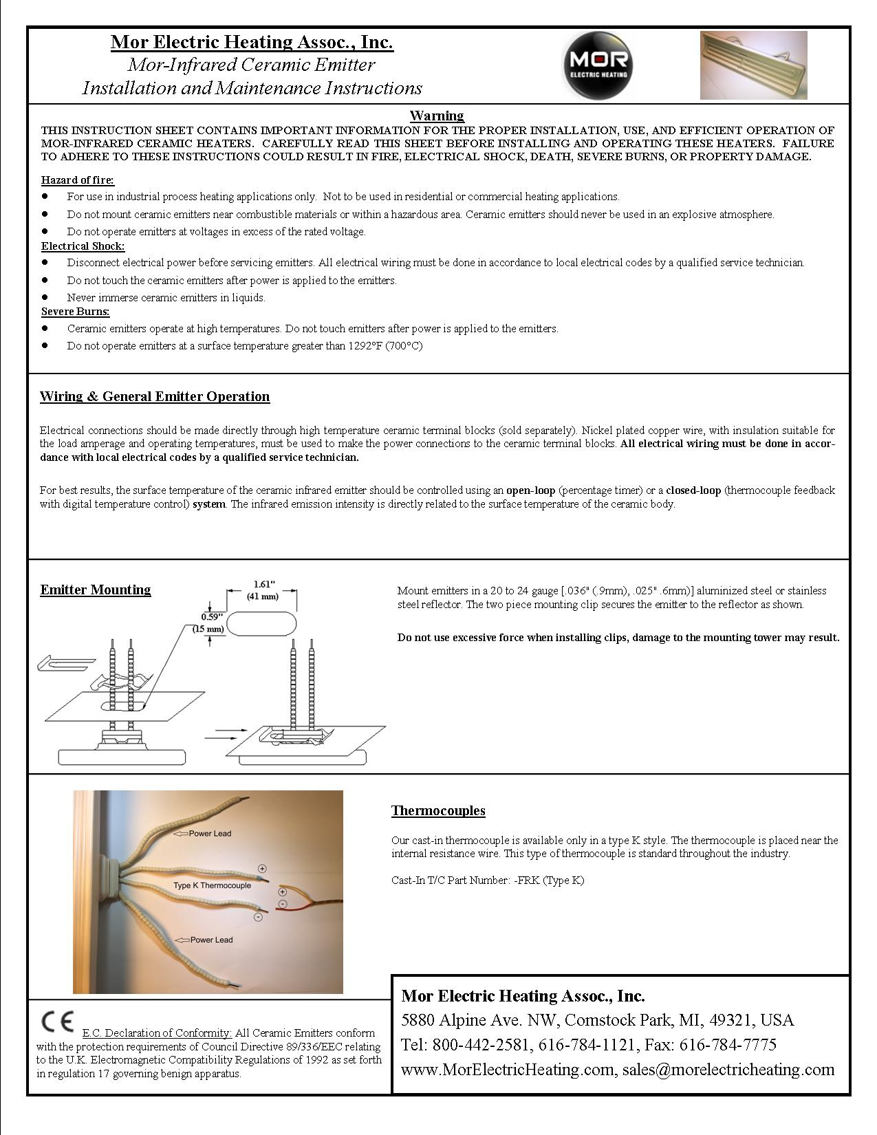
Ceramic Emitter Installation Instructions
|
|
You must have the free Adobe Acrobat Reader plug-in. |
|

E.C. Declaration of Conformity: All Salamander Ceramic Emitters conform with the
protection requirements of Council Directive 89/336/EEC relating to the U.K.
Electromagnetic Compatibility Regulations of 1992 as set forth in regulation 17 governing
benign apparatus.
Recognized to U.S. and
Canadian requirements under the Component Recognition Program of Underwriters Laboratory,
Inc. Up to 240 Volt Only.
Emitter Mounting, Single Tower

Emitter Mounting, Double Tower


Mount emitters in a 20 to 24 gauge [.036" (.9mm), .025" .6mm)] aluminized steel or stainless steel reflector. The single piece retaining clip(s) secures the emitter to the reflector as shown. Two piece mounting clips are available if required. Do not use excessive force when installing clips, damage to the mounting tower may result.
Wiring & General Emitter Operation
Electrical connections should be made directly through high temperature ceramic terminal blocks (sold separately). Nickel plated copper wire, with insulation suitable for the load amperage and operating temperatures, must be used to make the power connections to the ceramic terminal blocks. All electrical wiring must be done in accordance with local electrical codes by a qualified service technician.
For best results, the surface temperature of the Salamander ceramic infrared emitter should be controlled using an open-loop (percentage timer) or a closed-loop (thermocouple feedback with digital temperature control) system. The infrared emission intensity is directly related to the surface temperature of the ceramic body (see the Salamander technical manual for more details).
Incorporated into the front surface of the Salamander ceramic emitter is a red color changing decal. As the ceramic emitter increases in temperature this decal will begin to change from red to black (transition temperature is approximately 400°F (205°C)). The decal will remain "black" until the temperature of the emitter falls below the transition temperature where it will then return to its original red color. Along with the color changing decal, the emitters can also have color changing glaze. The yellow glaze will start to turn to a butterscotch/brown color at approximately 200°F (93°C).
Do not operate the Salamander ceramic emitters at a surface temperature greater than 1292°F (700°C).
ESES-Installation Instructions

The Salamander ESES (Solid Edison Screw Cap Emitter) must be installed into an appropriately sized porcelain Edison base and reflector. All electrical wiring must be done in accordance with local electrical codes by a qualified service technician.
Warning: Hazard of fire
do not mount emitters near combustible materials or within a hazardous area.
do not operate emitters at voltages in excess of the rated voltage.
Warning
Hazard of fire: Do not mount ceramic emitters near combustible materials or within a hazardous area. Ceramic emitters should never be used in an explosive atmosphere.
Electrical Shock: Disconnect electrical power before servicing emitters. All electrical wiring must be done in accordance to local electrical codes by a qualified service technician.
Do not touch the ceramic emitters after power is applied to the emitters.
Never immerse ceramic emitters in liquids.
Severe Burns: Ceramic emitters operate at high temperatures. Do not touch emitters after power is applied to the emitters.
*** Do not operate emitters at a surface temperature greater than 1292°F (700°C)
Thermocouples
Thermocouples are available in two standard configurations. The replaceable thermocouple (shown above), and the cast-in thermocouple. The replaceable thermocouple is a unique spring formed thermocouple specifically designed for the Salamander ceramic infrared emitter. It is available in type J or K style. The thermocouple is inserted into the thermowell located in the mounting tower of the emitter. The spring clip locks onto the shoulder of the mounting tower giving a secure and consistent thermocouple placement within the emitter. To remove the thermocouple simply release the spring clip and remove the thermocouple from the ceramic emitter.
The cast-in thermocouple is available only in a type K style. Since the thermocouple is placed near the internal resistance wire, the thermocouple is considered fast responding. This type of thermocouple is standard throughout the industry.
Replaceable T/C Part Number: J-24-A (Type
J) & K-24-A (Type K)
Cast-In T/C Part Number: -FRK (Type K)
|
We are a distributor of infrared heaters. Always consult manufacturers installation instructions for proper installation of the products or systems shown on this website. © Copyright 1999-2012 Mor Electric Heating Assoc., Inc. |
MOR
ELECTRIC HEATING ASSOC., INC. |
|