|
InfraredHeaters.com Questions? 1-800-442-2581 |
Our secure online
ordering website: www.MorElectricHeating.com.
|
| Home | Products | Accessories | Ordering | Contact Us | Search | ||
|
InfraredHeaters.com Questions? 1-800-442-2581 |
Our secure online
ordering website: www.MorElectricHeating.com.
|
| Home | Products | Accessories | Ordering | Contact Us | Search | ||
Reflector and Panel Information from Back Issues of The Salamander News
Salamander Radiant Emission Grid.
April, 1998 issue
Take Note of Reflector Thickness. May, 1998 issue
Installation Instructions for Ceramic
Emitters. June, 1998 issue
Custom Panel Design. June, 1999 issue
Sizing and Layout. November 2000 issue
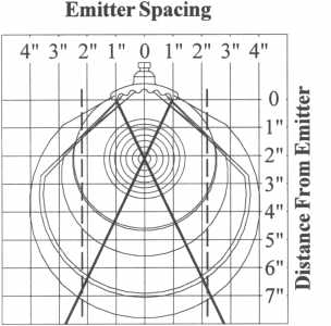 |
Salamander Radiant Emission Grid The Salamander radiant emission grid can be used to determine the proper ceramic emitter spacing when used in an application such as an infrared panel. In order to achieve an even heat pattern it is critical that the emitters are spaced so that their radiant emission patterns overlap when reaching the target. The more overlap that occurs, the more even the heat will be across the face of the product being heated. The area of highest radiant emission intensity for a single emitter is shown within the two dark crossed lines on the grid. In order for element emissions to overlap, the dashed line shows an intersection point at a distance of 7" will occur if the emitters are placed a distance of 2" apart from edge to edge. This same concept should be used to either determine the distance to place the product if using an existing panel, or placement of emitters if building a panel to guarantee radiant emission overlap. |
Take Note of Reflector Thickness
When using the single piece clip provided with each Salamander
ceramic element, attention must be given to the gauge and type of metal present in
both new and existing applications. Anything other than the accepted 20 to 24 gauge
(.036"-.025")(.9mm-.6mm) thickness of aluminized of stainless steel could result
in difficulty in securing the mounting clip. In some cases, unwarranted damage to the
towers could result if excessive force is used.
If you are having problems securing the clip, and are using the correct
gauge metal, care should be taken to check that the slot equals the recommended size of
15mm x 41mm (1.61" x .59").
If your reflector metal is thicker than the suggested gauge, a two
piece clip could be tried, but simply enlarging the slot could alleviate the problem.
Using the correct size slot allows more of the tower body to be accessible to the clip and
permit easier attachment.
If the slot is made too large, the elements may be loose causing
unwanted movement. A thin metal spacer placed between the clip and reflector should
tighten the connection. If the problem continues to exist, the sales office should be
contacted.
Salamander Ceramic Emitter
Installation Instructions

Mor Electric Heating Assoc.,
Inc.
5880 Alpine N.W., Comstock Park,
Michigan 49321, USA
Tel: 1-616-784-1121 or 1-800-442-2581
Fax: 1-616-784-7775
e-mail: sales@infraredheaters.com
![]() E.C. Declaration of Conformity: All Salamander Ceramic Emitters conform with the
protection requirements of Council Directive 89/336/EEC relating to the U.K.
Electromagnetic Compatibility Regulations of 1992 as set forth in regulation 17 governing
benign apparatus.
E.C. Declaration of Conformity: All Salamander Ceramic Emitters conform with the
protection requirements of Council Directive 89/336/EEC relating to the U.K.
Electromagnetic Compatibility Regulations of 1992 as set forth in regulation 17 governing
benign apparatus.
![]() Recognized to U.S. and Canadian
requirements under the Component Recognition Program of Underwriters Laboratory, Inc. Up
to 240 Volt Only.
Recognized to U.S. and Canadian
requirements under the Component Recognition Program of Underwriters Laboratory, Inc. Up
to 240 Volt Only.
Emitter Mounting, Single Tower
Emitter Mounting, Double Tower
Mount emitters in a 20 to 24 gauge [.036" (.9mm), .025" .6mm)] aluminized steel or stainless steel reflector. The single piece retaining clip(s) secures the emitter to the reflector as shown. Two piece mounting clips are available if required. Do not use excessive force when installing clips, damage to the mounting tower may result.
Wiring & General Emitter Operation
Electrical connections should be made directly through high temperature ceramic terminal blocks (sold separately). Nickel plated copper wire, with insulation suitable for the load amperage and operating temperatures, must be used to make the power connections to the ceramic terminal blocks. All electrical wiring must be done in accordance with local electrical codes by a qualified service technician.
For best results, the surface temperature of the Salamander ceramic infrared emitter should be controlled using an open-loop (percentage timer) or a closed-loop (thermocouple feedback with digital temperature control) system. The infrared emission intensity is directly related to the surface temperature of the ceramic body (see the Salamander technical manual for more details).
Incorporated into the front surface of the Salamander ceramic emitter is a red color changing decal. As the ceramic emitter increases in temperature this decal will begin to change from red to black (transition temperature is approximately 400°F (205°C)). The decal will remain "black" until the temperature of the emitter falls below the transition temperature where it will then return to its original red color. Along with the color changing decal, the emitters can also have color changing glaze. The yellow glaze will start to turn to a butterscotch/brown color at approximately 200°F (93°C).
Do not operate the Salamander ceramic emitters at a surface temperature greater than 1292°F (700°C).
ESE-Installation Instructions
The Salamander ESE (Solid Edison Screw Cap Emitter) must be installed into an appropriately sized porcelain Edison base, reflector, and guard (Part #: R/H/G). Nickel plated copper wire, with insulation suitable for the load amperage and operating temperatures, must be used to make the power connection to the porcelain Edison base. All electrical wiring must be done in accordance with local electrical codes by a qualified service technician.
Warning: Hazard of fire
do not mount emitters near combustible materials or within a hazardous area.
do not operate emitters at voltages in excess of the rated voltage.
Warning
Hazard of fire: Do not mount ceramic emitters near combustible materials or within a hazardous area. Ceramic emitters should never be used in an explosive atmosphere.
Electrical Shock: Disconnect electrical power before servicing emitters. All electrical wiring must be done in accordance to local electrical codes by a qualified service technician.
Do not touch the ceramic emitters after power is applied to the emitters.
Never immerse ceramic emitters in liquids.
Severe Burns: Ceramic emitters operate at high temperatures. Do not touch emitters after power is applied to the emitters.
*** Do not operate emitters at a surface temperature greater than 1292°F (700°C)
Thermocouples
Thermocouples are available in two standard configurations. The replaceable thermocouple (shown above), and the cast-in thermocouple. The replaceable thermocouple is a unique spring formed thermocouple specifically designed for the Salamander ceramic infrared emitter. It is available in type J or K style. The thermocouple is inserted into the thermowell located in the mounting tower of the emitter. The spring clip locks onto the shoulder of the mounting tower giving a secure and consistent thermocouple placement within the emitter. To remove the thermocouple simply release the spring clip and remove the thermocouple from the ceramic emitter.
The cast-in thermocouple is available only in a type K style. Since the thermocouple is placed near the internal resistance wire, the thermocouple is considered fast responding. This type of thermocouple is standard throughout the industry.
Replaceable T/C Part Number: J-24-A (Type
J) & K-24-A (Type K)
Cast-In T/C Part Number: -FRK (Type K)
June 1999 - Custom Design
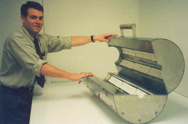
One of the advantages of a small company is that we have no problem doing things "your way." The above photo is of a recent oven fabrication designed for curing medical equipment in the production process.
The oven, designed to the customers specifications, by our engineer Mark Jackson, is simply composed of six SWB/R/A/3 reflector assemblies holding 18 FTE-400 elements. The fixtures are encased in a cylindrical stainless steel housing which opens in clam shell fashion.
The manufacturer, who wishes to remain anonymous due to the confidentiality of the process, supplied the basic concept parameters. The heating requirements and pattern were configured by our engineering staff and formed the basis for the finished product.
In this way, processes can be developed to conform to the end users exact needs. It’s fun, it’s exciting, and innovative to use the basic Salamander products to create a prototype piece of equipment exclusive to the customer, and easier than you may think. So, don’t hesitate to offer the customer the opportunity to do it "his way."
Sizing & Layout
The Information - Once a customer has decided to change over to or use ceramic heaters, their next question usually concerns sizing and layout. The engineering staff at Mor Electric Heating does this as routine and all distributors should be competent in providing this service. There are initially some basic questions to be answered:
1. Is this going to be a drying/evaporating application or
does the product need to be heated for processing?
2. Which type of oven is needed: stationary,
"batch", or conveyorized?
3. If it is a drying application, how much water or solvent
needs to be evaporated?
4. What temperature does the product need to be heated to?
5. How fast does the heating process need to be?
Additional product information is also needed such as, physical size, weight, material, color, and the ambient or "starting" temperature of the product, including specific heat and emissivity, if known.
Using this information, a heat loss may be calculated to determine the power required by using this basic formula:
Step 1
(w/hr)/(in2) = {(weight) (spec heat) (rT)}/3.412 Btu/w
However, knowing the power requirement is not enough. For radiant applications the emissivity must be factored in. Using the emissivity of the product and the estimated emissivity of the emitter in the following formula allows you to establish the "effective" or average emissivity between the two points.
Step 2
e = 1/(1/e1 + 1/e2 - 1)
e1 = emissivity of the source
e2 = emissivity of the target
Once the effective emissivity is know, the Stefan-Boltzmann Law is used to determine the source temperature of the emitter:
T1 = source temperature, e = effective emissivity, watt/in2 = the amount of kW needed
This information, combined with the space required, determines the number and wattage of the individual heaters required. Spacing between emitters is typically 1/4" (6mm) to 1" (25mm), and the emitters are placed in the heated area according to the zoning requirements of the application and the need to balance 3 phase loads. On the back of this newsletter is an example application done using these steps.
![]()
The Example - A request was received for heating information on an application requiring evaporating water from water-based adhesive applied to a wooden board before being able to adhere the finished surface to the board. Following the steps outlined on the previous page, the following is the how we arrived at the required information.
Information received from the customer:
1. This is obviously an evaporating application.
2. The oven will need to be conveyorized to the point that
it will be shuttling back and forth in front of a stationary product.
3. The amount of water needed to be evaporated is 2.5 grams
per sq. ft.
4. Because we are evaporating water, it needs to be heated
to 212° F.
5. 2.5 grams of water needed to be evaporated every 4
seconds.
Before going into step 1, the weight in grams had to be converted to pounds per square inch.
Step 1
(w/hr)in2 = {38.27 x 10⁻⁶ (1.0)(212-65)}3.412
(w/hr) in2= 1.65 x 10⁻³
When doing applications involving water evaporation the latent heat of vaporization must be considered and is determined by the following formula:
{965Btu/Lb(38.27 x 10-6)} 3.412= 10.82 x 10-3 = Latent heat evaporation
Add the wattage required to raise the heat with the latent heat of evaporation to find the
Total Power Required = (1.65 x 10⁻³) + (10.82 x 10⁻³) = 12.47 x 10⁻³ (watt/hr) / in2
Now that we have the power required we must adapt it to how fast the waters need to be evaporated, which was stated as every 4 seconds, by using the following formula:
warm up time = watt-hour/in2 x 60 min. (watt/in2)
watt/in2 = 12.47 x 10⁻³(60) /watt/in2 = 12.47 x 10⁻³(60)/ (4/60)= 11.223 watt/in2
Now that we have this information we are ready to solve for emissivity.
Step 2
e = 1 /. (1/.9 + 1/.93-1)
e =.84
Using the emissivity we move to the Stefan Boltzmann formula.
Step 3
T2 = (65+212)/2 = 332.5 Deg. K
A graph may be used to determine the element wattage required to reach the identified source temperature. Graphs such as this can be found in our Technical Manual or on our Internet website. In this case our 951°F indicates that we use 800-1000 watt FTE size elements. I chose to specify FTE-1000 elements knowing that they are a standard and typically stocked element.
Working with our heated area of 5 ft. x 30", and using FTE-1000 elements, spaced as recommended, we would need 91 elements. The customer stated no special zoning was required. Are you ready for the challenge?
|
We are a distributor of infrared heaters. Always consult manufacturers installation instructions for proper installation of the products or systems shown on this website. © Copyright 1999-2019 Mor Electric Heating Assoc., Inc. MOR
ELECTRIC HEATING ASSOC., INC. |
|